Components
Here is the list of components I am going to use:
Raspberry Pi 2 model
Heart and brains of the robot. I wanted to use the latest and fastest Raspberry in order to do all things at the same time as planned (keeping robot balanced, computer vision etc.).
Link: http://fi.rsdelivers.com/product/raspberry-pi/raspberry-pi-2-model-b/raspberry-pi-2-model-b/8326274.aspx

XBOX 360 Wireless Controller for Windows
This will be connected to Raspberry PI USB port. This will be one of the controlling methods I'll try.Link: http://www.microsoft.com/hardware/en-us/p/xbox-360-wireless-controller-for-windows
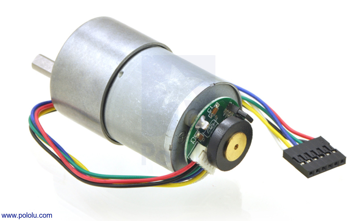
2 x Pololu 30:1 Metal Gearmotor 37Dx52L mm with 64 CPR Encoder
Two Pololu 37Dx52L motors with encoders.Link: https://www.pololu.com/product/1443
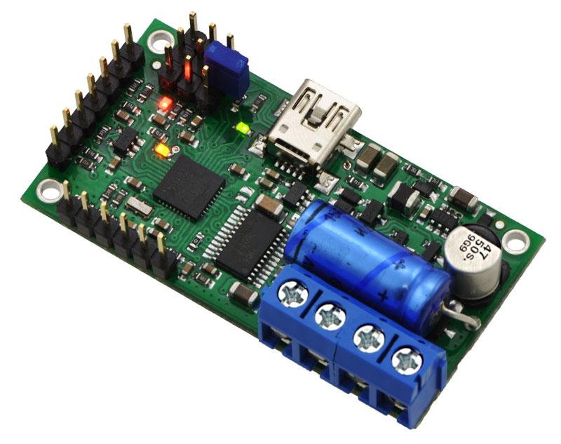
2 x Pololu Simple Motor Controller 18v7
Motor controllers. I selected these instead of simple H-bridge. In this project I'll connect these via USB or serial bus, I've tested with USB and seems to work. Analog control is not used for controlling motor so I can use the two ADC's for something else. I'll use 2 ADC's for IR distance measuring sensor unit which I tell next.. One ADC is used for measuring the Raspberry Pi power supply.Link: https://www.pololu.com/product/1372

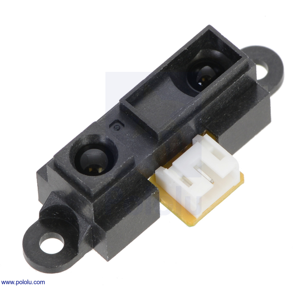
2 x GP2Y0A21YK0F distance measuring sensor unit
IR sensors for measuring front and back distances. Trying to avoid collisions.Link: http://www.sharpsma.com/webfm_send/1489.
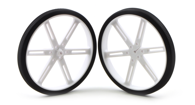
2 x Pololu Wheel 90×10mm Pair - White
Pair of wheels. Link: https://www.pololu.com/product/1439
Link: https://www.pololu.com/product/1083

Link: https://www.lrp.cc/en/products/vtec-batteries/stick-packs-7-cells/produkt/lrp-hyper-pack-4600-84v-7-zellen-nimh-stickpack/details/

Link: http://www.trust.com/en/all-products/19856-powerbank-4400--white

Link: Just find it from EBay

Link: Just find it from EBay

Gyro, Accelerometer, Compass for checking the robot position and tilting, Altimeter for checking whether the robot starts to fly in high speeds :P
Actually I ordered this component if I later build some quadcopter (don't tell my wife), that is why I got version with Altimeter. I can ofcourse use it as barometer and warn people about coming bad weather :)
Link: https://www.pololu.com/product/2470

I will use 2x middle size boards for creating the testing prototype. Two wooden blocks to top and bottom, then I'll screw the motors to bottom one. Then I'll screw the cutting boards to wooden blocks. If I am not cutting any holes for IR and camera those will be using the handle hole.
Link: http://www.biltema.fi/fi/Koti/Keittio/Leikkaaminen-pilkkominen-ja-raastaminen/Leikkuulaudat-sarjassa-3-2000018045/
Maybe some components added later. The first proto which I build is just for testing the setup and components. I will use normal kitchen cutting boards bought from Biltema and 2x 2x2 inch wooden blocks. Once I get it working, then I redesign the robot to be printed with 3D printer. As the 3D printing is very time consuming I don't want to print few days the prototype and then notice I missed something.. I hope building the prototype first avoids me to do mistakes in the 3D printed version, let's see.

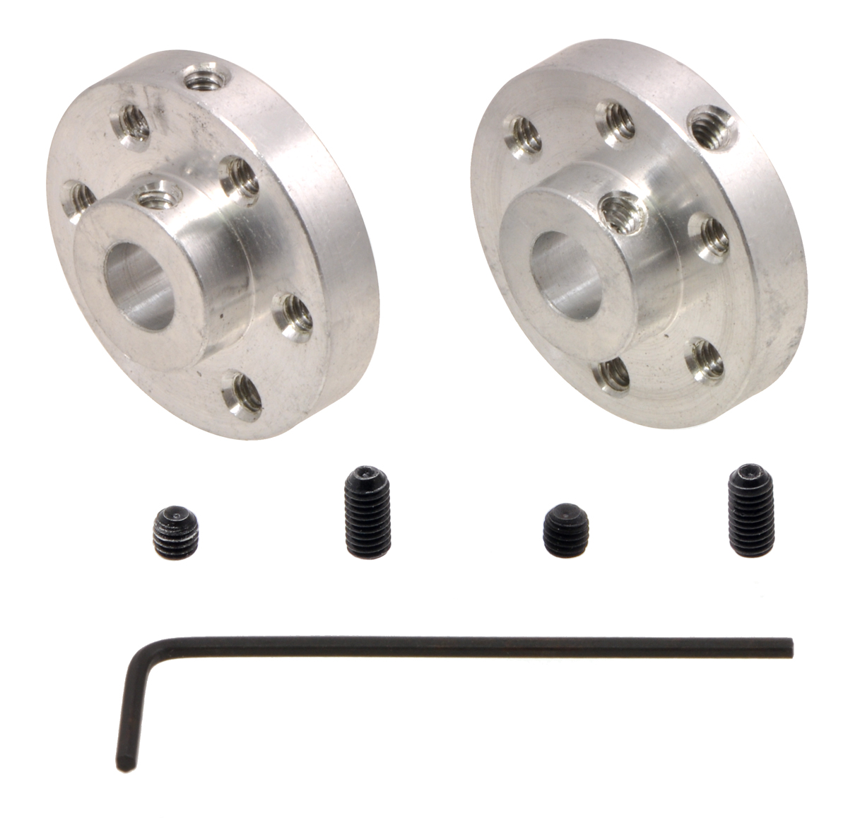
2 x Pololu Universal Aluminum Mounting Hub for 6mm Shaft, #4-40 Holes (2-Pack)
To attach wheels to motor shaft I need these mounting hubs.Link: https://www.pololu.com/product/1083

LRP Hyper Pack 4600 - 8.4V - 7-cell NiMH Stickpack
NiMH Battery for driving motors and motor controllers.Link: https://www.lrp.cc/en/products/vtec-batteries/stick-packs-7-cells/produkt/lrp-hyper-pack-4600-84v-7-zellen-nimh-stickpack/details/

Urban Revolt PowerBank 4400 mAh
5V, 1A Power Bank for driving Rasperry Pi.Link: http://www.trust.com/en/all-products/19856-powerbank-4400--white

128x64 pixels, 0.96" OLED Display, SPI controlled
Maybe I2C controlled would have been better but. Controlling can be changed in the PCB with resistors/jumpers. The display I'll use for debugging and later for eyes :D just for fun...Link: Just find it from EBay

2 x 5V Stepper Motors
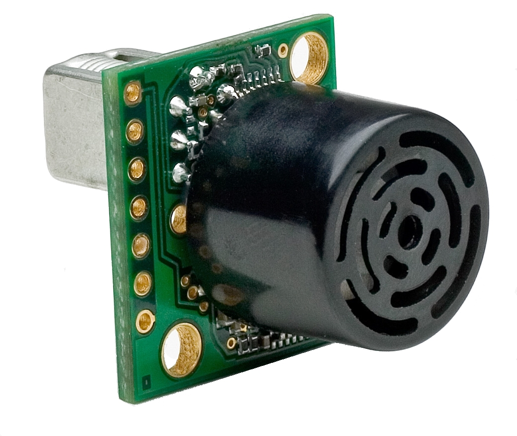
These stepper motors will be used for pan and tilt of the robot head. The head will contain the IR sensors, Raspberry Pi Camera, maybe the ultrasonic sensor (but I already have IR sensors so maybe I am not using it). Also it would be good to have some very bright LED's for the camera light. Otherwise the camera image is not very good when used in the dark.Link: Just find it from EBay

AltIMU-10 v4 Gyro, Accelerometer, Compass, and Altimeter (L3GD20H, LSM303D, and LPS25H Carrier)
Gyro, Accelerometer, Compass for checking the robot position and tilting, Altimeter for checking whether the robot starts to fly in high speeds :P
Actually I ordered this component if I later build some quadcopter (don't tell my wife), that is why I got version with Altimeter. I can ofcourse use it as barometer and warn people about coming bad weather :)
Link: https://www.pololu.com/product/2470

Biltema Cutting boards
I will use 2x middle size boards for creating the testing prototype. Two wooden blocks to top and bottom, then I'll screw the motors to bottom one. Then I'll screw the cutting boards to wooden blocks. If I am not cutting any holes for IR and camera those will be using the handle hole.
Link: http://www.biltema.fi/fi/Koti/Keittio/Leikkaaminen-pilkkominen-ja-raastaminen/Leikkuulaudat-sarjassa-3-2000018045/
Maybe some components added later. The first proto which I build is just for testing the setup and components. I will use normal kitchen cutting boards bought from Biltema and 2x 2x2 inch wooden blocks. Once I get it working, then I redesign the robot to be printed with 3D printer. As the 3D printing is very time consuming I don't want to print few days the prototype and then notice I missed something.. I hope building the prototype first avoids me to do mistakes in the 3D printed version, let's see.
Tests I've run this far..
- I can control motors using Python and C++. There is many parameters that can be configured to motor controllers, proper values needs to be found in testing. I already tuned start and stop timings so that running and stopping motor starts/stops smoothly and not in 0ms. Without this "smoothing" timing the motors give some "KLONK" noise which does not sound good.
- OLED display tested with Python library and C. Some problems in updating the screen. First screen write is more or less ok but next one is not.. Seems like bug in the used driver. Maybe the buffer that is written to the display is too small.. I need to debug it or write my own driver.
- Reading values from AltIMU-10 V4 has been tested but the results need to be filtered properly. What I've studied from internet the gyro readings need to be averaged and the timing of the readings is critical. So maybe I do some interrupt driven reading for the values.
- Sharp IR sensors are connected to Pololu 18V7 motor controller Analog Input Channel ADC's. Distance can be read.
- XBOX game controller tested with Python.
Tests to run before writing the actual code
Some tests to be run still are:- Connect encoders to Raspberry Pi and read encoder values. How to use these values in the code is not studied yet.
- Create circuit (voltage divider) for Urban Revolt PowerBank so that I can use one ADC from motor controller for monitoring the Raspberry Pi power power source. Idea is to measure the power source and when the voltage is getting too low, drive the robot into safe place and shut down gracefully. Later maybe drive the robot to charging station, but the circuit for doing the charging needs to be done first.
- Chaining of the motor controllers needs to be tested
- Controlling the motor controllers via TTL serial. For this I have level converters from 3.3V to 5V (not listed in above listing).
- Decide clever code architecture so that the components can be changed without affecting to the control logic.
- Controlling of the stepper motors. I saw nice 3D printed parts for making pan tilt with these steppers. Maybe I try the motors with that.

